Ok, this is a first post in my Guitar Wiring series.
In this we will explore the bass/treble cut component.
Normal tone control on a guitar cuts the treble. In some cases, especially when dealing with a bassy and boomy neck pickup, you might want to cut a little bit of bass.
Using push/pull or push-push pot you can achieve this.
So, here we use a standard control pot, it could be 250K or 300K or 500K , but I highly recommend using the logarithmic ones. They are marked as A, so it could be A250K or A500K.
I mostly use humbucker guitars so A500K is what I use most of the time.
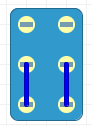
In the schematic below, this is the pulled-up position.
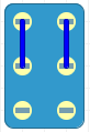
And this is the pushed down (default) position.
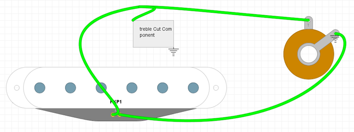
Now what is important to understand, the treble cut is usually connected to the path of the signal in parallel, like this:
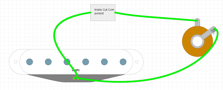
The bass cut , or the bass/treble cut we are building, has to be in series, like this:
In general, it can go before or after volume control, in my case I am doing it before volume control, otherwise there will be the 50s wiring,
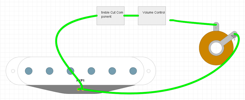
Anyways, here is the diagram:
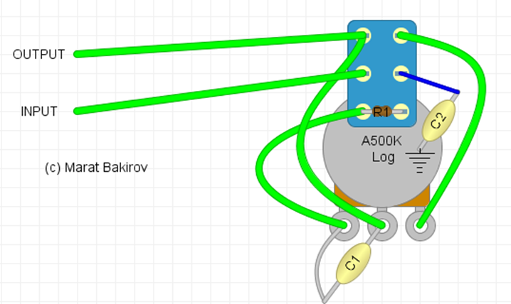
C1 is the bass cut capacitor, you can use any value usually depending on how much cut you want, usual range is about 680pf to 2 nf, the larger the value, the less cut you will have.
C2 is your normal treble cut capacitor, I usually use 22nf for bridge or 15nf for neck, but common range is about 15nf to 47nf.
R1 is an optional resistor.
If you don’t use it, then when switching to bass, there will be no treble cut whatsoever. (the usual treble cut control has some small amount of cut even in the fully open position). To retain the “minimum open” treble, cut, we can put the 500K resistor in here. (assuming the 500K pot). You can put a trimpot and experiment with the values.


Leave a Reply